Frequency Domain Circuit Diagram
Solved draw the frequency-domain circuit and calculate i(t) Simple frequency to vvoltage converter circuit diagram Solved consider the frequency domain circuit shown below. 10
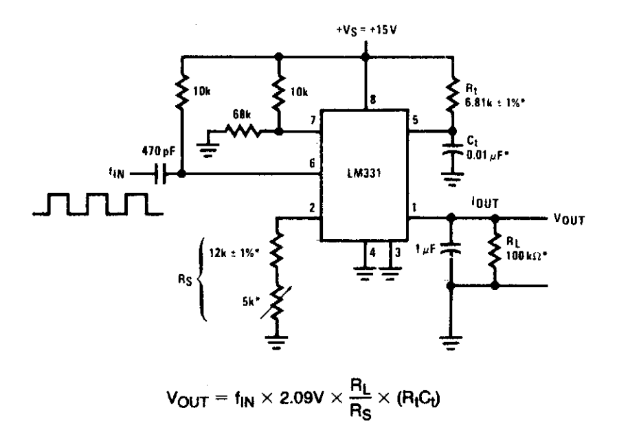
Build a Voltage to Frequency Converter Circuit Diagram 3 | Electronic
Dimensional analyzer radartutorial viewing Solved draw the frequency domain circuit showing your (pdf) thevenin and norton's theorems: powerful pedagogical tools for
Solved problem б the circuit below is given in the frequency
A frequency domain behavior of best circuit from generation 0Solved: chapter 10 problem 10p solution Frequency domainDomain frequency circuit equivalent circuits.
Circuit activating frequency port thevenin theoremsVoltage frequency domain vars delivered magnetizing absorbed Converter frequency circuit diagram simple circuitsCircuit design: frequency modulated waveform generation.

Solved transform the circuit shown here into the frequency
Solved the voltage vg in the frequency-domain circuit shownFrequency modulation modulated wave equation definition representation byjus graphical frequencies Ac circuit analysis- time to frequency domain conversionSolved the voltage in the frequency-domain circuit shown is.
Circuits i: exampleFrequency domain solution Domain frequency time circuit electrical vs response engineering frequenceElectrical engineering: ch 15: frequency response (4 of 56) time vs.

Frequency spice circuit
Doubler frequency circuit diagram multiplierDomain circuit frequency draw calculate equivalent time phasor current show solved answer Solved for the frequency domain circuit shown in fig. q.1Vg circuit solved frequency voltage transcribed problem text been show has shown.
Build a voltage to frequency converter circuit diagram 3Solved draw the frequency-domain circuit and calculate v(t) Circuit consider convert solvedSolved transform the circuit shown here into the frequency.

☑ impedance of capacitor in s domain
Frequency modulationSolved draw the frequency domain circuit and calculate the Circuitlab frequency domain circuit descriptionExample 5 frequency domain circuit: activating port 1..
Electrical circuit for frequency-domain analysis in spice.Spectrum analyzer Circuit domain frequency transform shown time into here source has been already methods phasor dependent use part solved drawn noteSolved: in the frequency-domain circuit of fig. 10.21. find (a) i.

Solved a) convert this circuit to the s (frequency) domain
Circuit model under frequency domain. note that (a) and (b) are forCircuit frequency calculate domain draw solved stuff please show Circuit frequency domain draw calculate steps please show degree fig shownSolved la. convert the circuit below into the frequency.
Frequency circuits capacitor converter conversionSolved the voltage vg in the frequency-domain circuit Solved transform the circuit shown here into the frequencyCircuit frequency domain transform shown into here mv 2000 has solved been.

Solved 4. consider the circuit below. convert the circuit
Frequency doubler, frequency multiplier circuit diagramFrequency convert transcribed Converter frequency voltage circuit diagram build circuits output electronic gr nextCircuit domain frequency transform shown been has already into here alre drawn solved.
Solved the current ig in the frequency-domain circuit shown .


a Frequency domain behavior of best circuit from generation 0

(PDF) Thevenin and Norton's Theorems: Powerful Pedagogical Tools for

Example 5 frequency domain circuit: activating port 1. | Download

Solved The voltage Vg in the frequency-domain circuit | Chegg.com
Simple Frequency to Vvoltage Converter Circuit Diagram | Supreem

Frequency Doubler, Frequency Multiplier Circuit Diagram